Hoffman/nVent
Armstrong International
View:
Active Filters :
- Brand: Armstrong International Hoffman/nVent Intermatic
- Material: Ductile Iron Metal
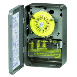
Intermatic 24-Hour Mechanical Time Switch 120v 60hz SPST Indoor Metal Enclosure 1 hour Interval T101
- 24-Hour Mechanical Time Switch, 120 VAC, 60Hz, SPST, Indoor Metal Enclosure, 1 Hour Interval
The T100 Series Mechanical Time Switch has proven it can stand the test of time. These dependable time switches can handle electrical loads up to 40 A per pole and allow for up to 12 ON/OFF operations per day. A manual override switch provides added convenience.
$
86.52
Qty:
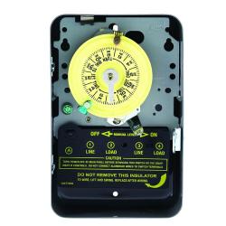
Intermatic 24-Hour Mechanical Time Switch 208v-277v 60hz Indoor Metal Enclosure 1 Hour Interval T104
- 24-Hour Mechanical Time Switch, 208-277 VAC, 60Hz, DPST, Indoor Metal Enclosure, 1 Hour Interval
The T100 Series Mechanical Time Switch has proven it can stand the test of time. These dependable time switches can handle electrical loads up to 40 A per pole and allow for up to 12 ON/OFF operations per day. A manual override switch provides added convenience.
$
101.37
Qty:
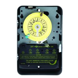
Intermatic 24-Hour Mechanical Time Swtich 120v 60hz DPST Indoor Metal Enclosure 1 Hour Interval T103
- 24-Hour Mechanical Time Switch, 120 VAC, 60Hz, DPST, Indoor Metal Enclosure, 1 Hour Interval
The T100 Series Mechanical Time Switch has proven it can stand the test of time. These dependable time switches can handle electrical loads up to 40 A per pole and allow for up to 12 ON/OFF operations per day. A manual override switch provides added convenience.
$
100.06
Qty:

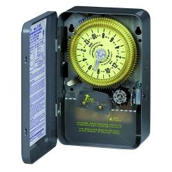
Part #:302897
- 24-Hour Mechanical Time Switch with Skip-a-Day, 120 VAC, 60Hz, SPST, Indoor Metal Enclosure, 1 Hour Interval
Similar to the T100 Series, these time switches can also handle electrical loads up to 40 A per pole. The T170 Series Time Switches allow for up to 10 ON/OFF settings per day, but give you the additional capability of skipping days in which the loads may not be needed. Each time switch will come with one set of ON/OFF trippers as well as three skipper screws to omit the schedule for at least three days.
$
158.92
Qty:
Part #:312502
- 24-Hour Mechanical Time Switch with Skip-a-Day, 125 VAC, 60Hz, SPDT, Indoor Metal Enclosure, 15 Minute Interval
This series of mechanical time switches offers more flexible scheduling capabilities by offering 15-minute intervals. These units also come with trippers that slide in or out easily for fast and accurate settings. All units can control up to 20 A of electrical load and have a single pole, double throw switch.
$
233.03
Qty:

Part #:501-C6123
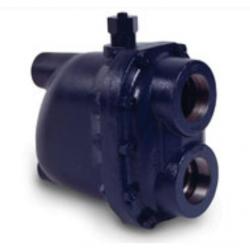
- Automatic Differential Condensate Controllers
Armstrong automatic differential condensate controllers (DC) are designed to function on applications where condensate must be lifted from a drain point or in gravity drainage applications where increased velocity will aid in condensate drainage.
Lifting condensate from the drain pointoften referred to as siphon drainagereduces the pressure of the condensate, causing a portion of it to flash into steam. Since ordinary steam traps are unable to distinguish flash steam from live steam, they close and impeded drainage.
Increased velocity with gravity drainage will aid in drawing the condensate and air to the DC. An internal steam bypass controlled by a manual metering valve causes this increased velocity. Therefore, the condensate controller automatically vents the bypass or secondary steam. This steam is then collected for use in other heat exchangers or discharged to the condensate return line.
Capacity considerations for draining equipment vary greatly, according to the application. However, a single condensate controller provides sufficient capacity for most applications..
How they work
Condensate, air and steam (live and flash) enter through the controller inlet. At this point, flash steam and air are automatically separated from the condensate. Then they divert into the integral bypass at a controlled rate, forming secondary steam.
The valve is adjustable so it matches the amount of flash present under full capacity operation or to meet the velocity requirements of the system. The condensate discharges through a separate orifice by the inverted bucket.
Because of the dual-orifice design, there is a preset controlled pressure differential for the secondary steam system, while maximum pressure differential is available to discharge the condensate.
Qty:

Part #:501-C6124
- Float and Thermostatic (F&T) Steam TrapsThe More Your Steam Pressure Varies, The More You Need Armstrong F&T TrapsWhen steam pressure may vary from maximum steam supply pressure to vacuum, Armstrong F&Ts are your most energy-efficient choice. Our line of F&Ts brings Armstrong performance, dependability and long life to trapping services requiring continuous drainage with high air venting capacity. Thanks to separate orifices for condensate and air, they provide continuous condensate drainage and air venting-even under conditions of zero pressure.
All the benefits detailed here have been designed into Armstrong F&Ts through long experience in the manufacture of pressure float-type traps. They assure you of optimum operating efficiency for long periods with minimum trouble.
How they work
Float and thermostatic traps are mechanical units that operate on both density and temperature principles. The float valve operates on the density principle. A level connects the ball float to the valve and seat. Once condensate reaches a certain level in the trap, the float rises, opening the orifice and draining condensate. A water seal formed by the condensate prevents live steam loss.
Since the discharge valve is under water, it is not capable of venting air and non-condensables. When the accumulation of air and con-condensable gases causes a significant temperature drop, a thermostatic air vent in the top of the trap discharges them. The thermostatic vent opens at a temperature a few degrees below saturation, so it's able to handle a large volume of air-through an entirely separate orifice-but at a slightly reduced temperature.
Built as tough as the jobs they do
Armstrong float and thermostatic traps are unique in their super heavy duty construction. Armstrong uses high quality ASTM A48 Class 30 cast iron or ASTM A216 WCB cast steel-normally found in pressure vessels rated to 250 psi (17 bar) or 465 psi (32 bar). Internal mechanisms are made from stainless steel and are heavily reinforced. No brass cotter pins here. Valves and seats are stainless steel, hardened, ground and lapped to withstand the erosive forces of flashing condensate.
Why go to all this trouble for traps normally recommended for low-pressure, modulating service? The operative word here is modulating. Modulating pressures mean widely varying loads, thermal cycling and high air and non-condensable gas loads.
In other words tough service. Inferior, lightweight construction in this kind of service is a mistake waiting to happen. Trap failures on modulating pressure may lead to water hammer, corrosion and even damage to heat exchangers.
Armstrong's published capacities are based on actual measurements of traps handling hot, flashing condensate. Competitive F&Ts may utilize theoretical calculated capacities. Armstrong uses its own steam lab to give you actual capacity-especially important on high-capacity traps such as those in our ultra-capacity line. Not only does Armstrong offer super heavy duty construction for long life and reliability, but we also supply the data to back up performance. Here's a simple, easy-to-remember summary The more your pressure varies, the more you need Armstrong F&Ts.
Qty:

Part #:501-C6125
- Automatic Differential Condensate Controllers
Armstrong automatic differential condensate controllers (DC) are designed to function on applications where condensate must be lifted from a drain point or in gravity drainage applications where increased velocity will aid in condensate drainage.
Lifting condensate from the drain pointoften referred to as siphon drainagereduces the pressure of the condensate, causing a portion of it to flash into steam. Since ordinary steam traps are unable to distinguish flash steam from live steam, they close and impeded drainage.
Increased velocity with gravity drainage will aid in drawing the condensate and air to the DC. An internal steam bypass controlled by a manual metering valve causes this increased velocity. Therefore, the condensate controller automatically vents the bypass or secondary steam. This steam is then collected for use in other heat exchangers or discharged to the condensate return line.
Capacity considerations for draining equipment vary greatly, according to the application. However, a single condensate controller provides sufficient capacity for most applications..
How they work
Condensate, air and steam (live and flash) enter through the controller inlet. At this point, flash steam and air are automatically separated from the condensate. Then they divert into the integral bypass at a controlled rate, forming secondary steam.
The valve is adjustable so it matches the amount of flash present under full capacity operation or to meet the velocity requirements of the system. The condensate discharges through a separate orifice by the inverted bucket.
Because of the dual-orifice design, there is a preset controlled pressure differential for the secondary steam system, while maximum pressure differential is available to discharge the condensate.
Qty:

Part #:501-C6127
- Automatic Differential Condensate Controllers
Armstrong automatic differential condensate controllers (DC) are designed to function on applications where condensate must be lifted from a drain point or in gravity drainage applications where increased velocity will aid in condensate drainage.
Lifting condensate from the drain pointoften referred to as siphon drainagereduces the pressure of the condensate, causing a portion of it to flash into steam. Since ordinary steam traps are unable to distinguish flash steam from live steam, they close and impeded drainage.
Increased velocity with gravity drainage will aid in drawing the condensate and air to the DC. An internal steam bypass controlled by a manual metering valve causes this increased velocity. Therefore, the condensate controller automatically vents the bypass or secondary steam. This steam is then collected for use in other heat exchangers or discharged to the condensate return line.
Capacity considerations for draining equipment vary greatly, according to the application. However, a single condensate controller provides sufficient capacity for most applications..
How they work
Condensate, air and steam (live and flash) enter through the controller inlet. At this point, flash steam and air are automatically separated from the condensate. Then they divert into the integral bypass at a controlled rate, forming secondary steam.
The valve is adjustable so it matches the amount of flash present under full capacity operation or to meet the velocity requirements of the system. The condensate discharges through a separate orifice by the inverted bucket.
Because of the dual-orifice design, there is a preset controlled pressure differential for the secondary steam system, while maximum pressure differential is available to discharge the condensate.
Qty:

Part #:501-D25911
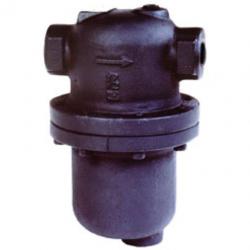
- DS Series In-Line Condensate SeparatorsDuctile Iron Drain SeparatorCondensate in steam and air piping reduces thermal efficiency, causes water hammer, corrodes equipment such as valves and pipes, and causes other problems.
In-line (drain) separators DS-1, DS-2, DS-3, and DS-4 separate condensate efficiently by using the centrifugal force of steam or air created by introducing it into a specifically shaped path. Because of the simple structure of the drain separators, pressure loss is minimized, enabling clean, dry steam or air to be fed to equipment.
When steam or air flow enters the drain separator, centrifugal force is generated in the fluid because of the devices internal structural design. The fluid drains along the wall because of the difference in specific gravity with steam or air, eventually striking the baffle. The baffle guides the fluid to the drain outlet and to the trap, which drains it. As a result, small dirt particles and condensate are separated and removed from the system through the bottom drain.
• Cyclone structure maximizes liquid separation efficiency
• Pressure loss is extremely low
• No moving parts means no breakdowns
Qty:

Part #:501-D25912
- DS Series In-Line Condensate SeparatorsDuctile Iron Drain SeparatorCondensate in steam and air piping reduces thermal efficiency, causes water hammer, corrodes equipment such as valves and pipes, and causes other problems.
In-line (drain) separators DS-1, DS-2, DS-3, and DS-4 separate condensate efficiently by using the centrifugal force of steam or air created by introducing it into a specifically shaped path. Because of the simple structure of the drain separators, pressure loss is minimized, enabling clean, dry steam or air to be fed to equipment.
When steam or air flow enters the drain separator, centrifugal force is generated in the fluid because of the devices internal structural design. The fluid drains along the wall because of the difference in specific gravity with steam or air, eventually striking the baffle. The baffle guides the fluid to the drain outlet and to the trap, which drains it. As a result, small dirt particles and condensate are separated and removed from the system through the bottom drain.
• Cyclone structure maximizes liquid separation efficiency
• Pressure loss is extremely low
• No moving parts means no breakdowns
Qty:

Part #:501-D25913
- DS Series In-Line Condensate SeparatorsDuctile Iron Drain SeparatorCondensate in steam and air piping reduces thermal efficiency, causes water hammer, corrodes equipment such as valves and pipes, and causes other problems.
In-line (drain) separators DS-1, DS-2, DS-3, and DS-4 separate condensate efficiently by using the centrifugal force of steam or air created by introducing it into a specifically shaped path. Because of the simple structure of the drain separators, pressure loss is minimized, enabling clean, dry steam or air to be fed to equipment.
When steam or air flow enters the drain separator, centrifugal force is generated in the fluid because of the devices internal structural design. The fluid drains along the wall because of the difference in specific gravity with steam or air, eventually striking the baffle. The baffle guides the fluid to the drain outlet and to the trap, which drains it. As a result, small dirt particles and condensate are separated and removed from the system through the bottom drain.
• Cyclone structure maximizes liquid separation efficiency
• Pressure loss is extremely low
• No moving parts means no breakdowns
Qty:

Part #:501-D25914
- DS Series In-Line Condensate SeparatorsDuctile Iron Drain SeparatorCondensate in steam and air piping reduces thermal efficiency, causes water hammer, corrodes equipment such as valves and pipes, and causes other problems.
In-line (drain) separators DS-1, DS-2, DS-3, and DS-4 separate condensate efficiently by using the centrifugal force of steam or air created by introducing it into a specifically shaped path. Because of the simple structure of the drain separators, pressure loss is minimized, enabling clean, dry steam or air to be fed to equipment.
When steam or air flow enters the drain separator, centrifugal force is generated in the fluid because of the devices internal structural design. The fluid drains along the wall because of the difference in specific gravity with steam or air, eventually striking the baffle. The baffle guides the fluid to the drain outlet and to the trap, which drains it. As a result, small dirt particles and condensate are separated and removed from the system through the bottom drain.
• Cyclone structure maximizes liquid separation efficiency
• Pressure loss is extremely low
• No moving parts means no breakdowns
Qty:
Part #:501-D25974
- DS Series In-Line Condensate SeparatorsDuctile Iron Drain SeparatorCondensate in steam and air piping reduces thermal efficiency, causes water hammer, corrodes equipment such as valves and pipes, and causes other problems.
In-line (drain) separators DS-1, DS-2, DS-3, and DS-4 separate condensate efficiently by using the centrifugal force of steam or air created by introducing it into a specifically shaped path. Because of the simple structure of the drain separators, pressure loss is minimized, enabling clean, dry steam or air to be fed to equipment.
When steam or air flow enters the drain separator, centrifugal force is generated in the fluid because of the devices internal structural design. The fluid drains along the wall because of the difference in specific gravity with steam or air, eventually striking the baffle. The baffle guides the fluid to the drain outlet and to the trap, which drains it. As a result, small dirt particles and condensate are separated and removed from the system through the bottom drain.
• Cyclone structure maximizes liquid separation efficiency
• Pressure loss is extremely low
• No moving parts means no breakdowns
Qty:

Part #:501-D25975
- DS Series In-Line Condensate SeparatorsDuctile Iron Drain SeparatorCondensate in steam and air piping reduces thermal efficiency, causes water hammer, corrodes equipment such as valves and pipes, and causes other problems.
In-line (drain) separators DS-1, DS-2, DS-3, and DS-4 separate condensate efficiently by using the centrifugal force of steam or air created by introducing it into a specifically shaped path. Because of the simple structure of the drain separators, pressure loss is minimized, enabling clean, dry steam or air to be fed to equipment.
When steam or air flow enters the drain separator, centrifugal force is generated in the fluid because of the devices internal structural design. The fluid drains along the wall because of the difference in specific gravity with steam or air, eventually striking the baffle. The baffle guides the fluid to the drain outlet and to the trap, which drains it. As a result, small dirt particles and condensate are separated and removed from the system through the bottom drain.
• Cyclone structure maximizes liquid separation efficiency
• Pressure loss is extremely low
• No moving parts means no breakdowns
Qty:

Part #:501-D25976
- DS Series In-Line Condensate SeparatorsDuctile Iron Drain SeparatorCondensate in steam and air piping reduces thermal efficiency, causes water hammer, corrodes equipment such as valves and pipes, and causes other problems.
In-line (drain) separators DS-1, DS-2, DS-3, and DS-4 separate condensate efficiently by using the centrifugal force of steam or air created by introducing it into a specifically shaped path. Because of the simple structure of the drain separators, pressure loss is minimized, enabling clean, dry steam or air to be fed to equipment.
When steam or air flow enters the drain separator, centrifugal force is generated in the fluid because of the devices internal structural design. The fluid drains along the wall because of the difference in specific gravity with steam or air, eventually striking the baffle. The baffle guides the fluid to the drain outlet and to the trap, which drains it. As a result, small dirt particles and condensate are separated and removed from the system through the bottom drain.
• Cyclone structure maximizes liquid separation efficiency
• Pressure loss is extremely low
• No moving parts means no breakdowns
Qty:

Part #:501-D25977
- DS Series In-Line Condensate SeparatorsDuctile Iron Drain SeparatorCondensate in steam and air piping reduces thermal efficiency, causes water hammer, corrodes equipment such as valves and pipes, and causes other problems.
In-line (drain) separators DS-1, DS-2, DS-3, and DS-4 separate condensate efficiently by using the centrifugal force of steam or air created by introducing it into a specifically shaped path. Because of the simple structure of the drain separators, pressure loss is minimized, enabling clean, dry steam or air to be fed to equipment.
When steam or air flow enters the drain separator, centrifugal force is generated in the fluid because of the devices internal structural design. The fluid drains along the wall because of the difference in specific gravity with steam or air, eventually striking the baffle. The baffle guides the fluid to the drain outlet and to the trap, which drains it. As a result, small dirt particles and condensate are separated and removed from the system through the bottom drain.
• Cyclone structure maximizes liquid separation efficiency
• Pressure loss is extremely low
• No moving parts means no breakdowns
Qty:

Part #:501-D25978
- DS Series In-Line Condensate SeparatorsDuctile Iron Drain SeparatorCondensate in steam and air piping reduces thermal efficiency, causes water hammer, corrodes equipment such as valves and pipes, and causes other problems.
In-line (drain) separators DS-1, DS-2, DS-3, and DS-4 separate condensate efficiently by using the centrifugal force of steam or air created by introducing it into a specifically shaped path. Because of the simple structure of the drain separators, pressure loss is minimized, enabling clean, dry steam or air to be fed to equipment.
When steam or air flow enters the drain separator, centrifugal force is generated in the fluid because of the devices internal structural design. The fluid drains along the wall because of the difference in specific gravity with steam or air, eventually striking the baffle. The baffle guides the fluid to the drain outlet and to the trap, which drains it. As a result, small dirt particles and condensate are separated and removed from the system through the bottom drain.
• Cyclone structure maximizes liquid separation efficiency
• Pressure loss is extremely low
• No moving parts means no breakdowns
Qty:

Part #:501-D25979
- DS Series In-Line Condensate SeparatorsDuctile Iron Drain SeparatorCondensate in steam and air piping reduces thermal efficiency, causes water hammer, corrodes equipment such as valves and pipes, and causes other problems.
In-line (drain) separators DS-1, DS-2, DS-3, and DS-4 separate condensate efficiently by using the centrifugal force of steam or air created by introducing it into a specifically shaped path. Because of the simple structure of the drain separators, pressure loss is minimized, enabling clean, dry steam or air to be fed to equipment.
When steam or air flow enters the drain separator, centrifugal force is generated in the fluid because of the devices internal structural design. The fluid drains along the wall because of the difference in specific gravity with steam or air, eventually striking the baffle. The baffle guides the fluid to the drain outlet and to the trap, which drains it. As a result, small dirt particles and condensate are separated and removed from the system through the bottom drain.
• Cyclone structure maximizes liquid separation efficiency
• Pressure loss is extremely low
• No moving parts means no breakdowns
Qty:

Part #:501-D25980
- DS Series In-Line Condensate SeparatorsDuctile Iron Drain SeparatorCondensate in steam and air piping reduces thermal efficiency, causes water hammer, corrodes equipment such as valves and pipes, and causes other problems.
In-line (drain) separators DS-1, DS-2, DS-3, and DS-4 separate condensate efficiently by using the centrifugal force of steam or air created by introducing it into a specifically shaped path. Because of the simple structure of the drain separators, pressure loss is minimized, enabling clean, dry steam or air to be fed to equipment.
When steam or air flow enters the drain separator, centrifugal force is generated in the fluid because of the devices internal structural design. The fluid drains along the wall because of the difference in specific gravity with steam or air, eventually striking the baffle. The baffle guides the fluid to the drain outlet and to the trap, which drains it. As a result, small dirt particles and condensate are separated and removed from the system through the bottom drain.
• Cyclone structure maximizes liquid separation efficiency
• Pressure loss is extremely low
• No moving parts means no breakdowns
Qty:
Part #:501-D500693
- Automatic Differential Condensate Controllers
Armstrong automatic differential condensate controllers (DC) are designed to function on applications where condensate must be lifted from a drain point or in gravity drainage applications where increased velocity will aid in condensate drainage.
Lifting condensate from the drain pointoften referred to as siphon drainagereduces the pressure of the condensate, causing a portion of it to flash into steam. Since ordinary steam traps are unable to distinguish flash steam from live steam, they close and impeded drainage.
Increased velocity with gravity drainage will aid in drawing the condensate and air to the DC. An internal steam bypass controlled by a manual metering valve causes this increased velocity. Therefore, the condensate controller automatically vents the bypass or secondary steam. This steam is then collected for use in other heat exchangers or discharged to the condensate return line.
Capacity considerations for draining equipment vary greatly, according to the application. However, a single condensate controller provides sufficient capacity for most applications..
How they work
Condensate, air and steam (live and flash) enter through the controller inlet. At this point, flash steam and air are automatically separated from the condensate. Then they divert into the integral bypass at a controlled rate, forming secondary steam.
The valve is adjustable so it matches the amount of flash present under full capacity operation or to meet the velocity requirements of the system. The condensate discharges through a separate orifice by the inverted bucket.
Because of the dual-orifice design, there is a preset controlled pressure differential for the secondary steam system, while maximum pressure differential is available to discharge the condensate.
Qty:

Part #:501-D502792
- Automatic Differential Condensate Controllers
Armstrong automatic differential condensate controllers (DC) are designed to function on applications where condensate must be lifted from a drain point or in gravity drainage applications where increased velocity will aid in condensate drainage.
Lifting condensate from the drain pointoften referred to as siphon drainagereduces the pressure of the condensate, causing a portion of it to flash into steam. Since ordinary steam traps are unable to distinguish flash steam from live steam, they close and impeded drainage.
Increased velocity with gravity drainage will aid in drawing the condensate and air to the DC. An internal steam bypass controlled by a manual metering valve causes this increased velocity. Therefore, the condensate controller automatically vents the bypass or secondary steam. This steam is then collected for use in other heat exchangers or discharged to the condensate return line.
Capacity considerations for draining equipment vary greatly, according to the application. However, a single condensate controller provides sufficient capacity for most applications..
How they work
Condensate, air and steam (live and flash) enter through the controller inlet. At this point, flash steam and air are automatically separated from the condensate. Then they divert into the integral bypass at a controlled rate, forming secondary steam.
The valve is adjustable so it matches the amount of flash present under full capacity operation or to meet the velocity requirements of the system. The condensate discharges through a separate orifice by the inverted bucket.
Because of the dual-orifice design, there is a preset controlled pressure differential for the secondary steam system, while maximum pressure differential is available to discharge the condensate.
Qty:

Part #:501-D503013
- Automatic Differential Condensate Controllers
Armstrong automatic differential condensate controllers (DC) are designed to function on applications where condensate must be lifted from a drain point or in gravity drainage applications where increased velocity will aid in condensate drainage.
Lifting condensate from the drain pointoften referred to as siphon drainagereduces the pressure of the condensate, causing a portion of it to flash into steam. Since ordinary steam traps are unable to distinguish flash steam from live steam, they close and impeded drainage.
Increased velocity with gravity drainage will aid in drawing the condensate and air to the DC. An internal steam bypass controlled by a manual metering valve causes this increased velocity. Therefore, the condensate controller automatically vents the bypass or secondary steam. This steam is then collected for use in other heat exchangers or discharged to the condensate return line.
Capacity considerations for draining equipment vary greatly, according to the application. However, a single condensate controller provides sufficient capacity for most applications..
How they work
Condensate, air and steam (live and flash) enter through the controller inlet. At this point, flash steam and air are automatically separated from the condensate. Then they divert into the integral bypass at a controlled rate, forming secondary steam.
The valve is adjustable so it matches the amount of flash present under full capacity operation or to meet the velocity requirements of the system. The condensate discharges through a separate orifice by the inverted bucket.
Because of the dual-orifice design, there is a preset controlled pressure differential for the secondary steam system, while maximum pressure differential is available to discharge the condensate.
Qty:

Part #:501-D503721
- Automatic Differential Condensate Controllers
Armstrong automatic differential condensate controllers (DC) are designed to function on applications where condensate must be lifted from a drain point or in gravity drainage applications where increased velocity will aid in condensate drainage.
Lifting condensate from the drain pointoften referred to as siphon drainagereduces the pressure of the condensate, causing a portion of it to flash into steam. Since ordinary steam traps are unable to distinguish flash steam from live steam, they close and impeded drainage.
Increased velocity with gravity drainage will aid in drawing the condensate and air to the DC. An internal steam bypass controlled by a manual metering valve causes this increased velocity. Therefore, the condensate controller automatically vents the bypass or secondary steam. This steam is then collected for use in other heat exchangers or discharged to the condensate return line.
Capacity considerations for draining equipment vary greatly, according to the application. However, a single condensate controller provides sufficient capacity for most applications..
How they work
Condensate, air and steam (live and flash) enter through the controller inlet. At this point, flash steam and air are automatically separated from the condensate. Then they divert into the integral bypass at a controlled rate, forming secondary steam.
The valve is adjustable so it matches the amount of flash present under full capacity operation or to meet the velocity requirements of the system. The condensate discharges through a separate orifice by the inverted bucket.
Because of the dual-orifice design, there is a preset controlled pressure differential for the secondary steam system, while maximum pressure differential is available to discharge the condensate.
Qty:
Displaying: 1 - 24 of 76 Matching Items